What is this? These are modular hand-made very flexible Red-Green-Blue LED display panels, 16x16 each. Every piece is hand-wired and hand-soldered together, even the control circuitry! You can wear one on your chest and/or back for a dynamic shirt or top to display your mood. A pillow for a fun couch. Put one in the back of your car window (you can see through it) and tell that **** what you really think. Wear one as an attention-grabbing safety device. On your head as a dynamic LED masquerade face-mask. Put several together and have a full-body LED suit! Anything, really!
When viewed by the naked eye, the tri-color LED panels appear to shift color depending on which angle you are viewing me. I do wear a thin white shirt over it at times to diffuse the colors making them more discernible, however the color shift effect goes away when this is done. I carry with me pairs of Diffraction Grating glasses (a.k.a. Firework Glasses, Rainbow Glasses, Laser Glasses, X-Ray Glasses) to enhance the sober's viewing experience. The panels are even capable of displaying multicolored animations/images and text, allowing me a wide range of bedazzlements!
Burning Man 2012 @ Black Rock City, Black Rock Desert, NV
Wed-Sun 12.08.29-12.09.02 (2 persons: various configurations)
Gentlemen of the Road @ Fairgrounds, Monterey, CA
Sat 12.08.25 (2 persons: 1 panel chest; 1 panel chest and back)
Outside Lands 2012 @ Golden Gate Park, San Francisco, CA
Fri-Sun 12.08.10-12.08.12 (2 persons: 1 panel chest; 1 panel chest and back)
Las Vegas Blvd. @ Las Vegas, NV
Sat 12.07.28 (1 panel on my chest)
TV of Tomorrow Show 2012 @ Yerba Buena Center for the Arts, San Francisco, CA
Tue-Wed 12.06.12-12.06.13 (Hanging array of 3 inter-connectd WiFi panels)
Maker Faire 2012 @ San Mateo County Expo Center, San Mateo, CA
Thu-Sun 12.05.17-12.05.20 (2 persons: Everywhere!)
Coachella Valley Music and Arts Festival 2012 @ Empire Polo Fields, Indio, CA
Thu-Sun 12.04.12-12.04.15 (3 persons: 1 person; 1 each wrist, 1 each ankle, 1 front, 1 back - 2 people; chest)
Creators Project S.F.: 2012 @ Fort Mason, San Francisco, CA
Sat 12.03.17 (2 persons: 1 person; 2 chest, 2 back, 1/ea arm, 1/ea calf - 1 person chest and back)
GLOW: A Festival of Fire and Light @ Museum of Art & History, Santa Cruz, CA
Fri 12.03.16 (2 persons: 1 person; 2 down chest, 2 down back, 1 each arm - 1 person; chest and back)
Sea of Dreams New Years Eve 2012 @ Concourse Exhibition Center, San Francisco, CA
Sat-Sun 11.12.31-12.01.01 (2 persons: 1 person; mask - 1 person; mask, 2 down chest, 2 down back)
Exploratorium's After Dark: Glow @ Palace of Fine Arts, San Francisco, CA
Thu 11.12.01 (2 persons: 1 person; 2 down chest, 2 down back - 1 person; 1 on chest, 1 on back)
MASQUEROTICA 2011 @ Concourse Exhibition Center, San Francisco, CA
Sat-Sun 11.10.22-11.10.23 (7 persons: 2 people; head - 2 dancers; arm cuffs - 1 dancer; collar - 2 dancers; chests)
With The Lumen Naughty (Fou Fou Ha)
Treasure Island Music Festival 2011 @ Treasure Island, San Francisco, CA
Sat-Sun 11.10.15-11.10.16 (4 persons: 2 panels; chest and back - 2 people; chest - 1 person; back)
ALR Client Appreciation Ball @ Bently Reserve, San Francisco, CA
Thu 11.10.13 (6 persons: 2 panels; chest and back - 2 dancers; arm cuffs - 1 dancer; collar - 2 dancers; chests)
With The Lumen Naughty (Fou Fou Ha)
NextGen Science Fair 2011 @ Fort Mason, San Francisco, CA
Sun-Mon 11.06.19-11.06.20 (6 panels; 2 down chest, 4 free-floating)
Lightning in a Bottle 2011 @ Silverado, CA
Sun-Mon 11.05.29-11.05.30 (8 panels; 2 down chest, 2 down back, 1 each thigh, 1 each upper arm)
Maker Faire 2011 @ San Mateo County Expo Center, San Mateo, CA
Fri-Sun 11.05.20-11.05.22 (10 panels; 2 down chest, 2 down back, 1 each arm, 1 each thigh, 2 free-floating)
Sea of Dreams New Years Eve 2011 @ Concourse Exhibition Center, San Francisco, CA
Fri-Sat 10.12.31-11.01.01 (6 panels; 2 down chest, 2 down back, 1 each upper arm)
Treasure Island Music Festival 2010 @ Treasure Island, San Francisco, CA
Sat-Sun 10.10.16-10.10.17 (8 panels; 2 down chest, 2 down back, 1 each thigh, 1 each calf)
Superhero Street Fair 2010 @ Waterfront, San Francisco, CA
Sat 10.07.10 (4 panels; 2 down chest, 2 down back)
Maker Faire 2010 @ San Mateo County Expo Center, San Mateo, CA
Sat-Sun 10.05.22-10.05.23 (6 panels; wrapped around torso)
LoveTech @ Il Pirata, San Francisco, CA
Sat 10.04.24 (6 panels; wrapped around torso)
Light Bright!
Light Dude
OMG!
Shirt Guy
Light Shirt
Glow Man
LED Shirt
LED Vest
Light Vest
Light Dress *
LED Skirt *
Light Coat
Light Armor
LED Corset *
LED Suit
LED Chainmail
* In the 6-panel torso wrap apparently it looks like a cocktail dress? In the blogs/press:
Treasure Island Music Festival 2009 led shirt guy
via babybloo 2009-10-19
Common Questions, most asked at top:
Are the LEDs waterproof?
They seem to be! I've sweat while wearing them and not because they are warm, mind you. I encase the logic in hotglue, but the LED undersides are exposed. Stay tuned I've been thinking of throwing one into a full bath just to see what happens and will post the video!
Are those charlieplexed?
Wow, this must be the phrase-du-jour for Maker Faire. No, these are your basic multiplexed matrix.
Are those Christmas lights?
No, they are RGB LEDs.
Are you an engineer?
Kinda sorta not really no... I am primarily a software engineer - rather software developer, and just a tinkerer in electronics by hobby. I have no certifications or formal education* for either.
Can I have your babies?
Let's go behind those porto-loos and see what we can work out!
Can you make me one?
It takes a LOT of time to manually produce these by hand, but may be available for sale as-is for a price. E-mail me and/or follow me on facebook/twitter.
Did you make that?
Yep! All hand-made from scratch, no pre-fab modules or circuits.
Do you have/know where I can find E/X/Mollies/MDMA/Rolls/Goodies/Pills/etc.?
No.
Have/Do/Will you go to Burning Man?
No. I've wanted to go for years, but I've never been. I popped my burning cherry 2012!
How are the panels interfaced?
It is a parallel signal, I suppose, something I made up; only 4 wires are needed to fully address each panel: Clock, Red, Green, Blue. I use two more in my design, Reset(V-Sync) and Memory Write. Those two are not required if driving them directly.
How did you make that?
Lots of wire cutting, weaving, soldering and... time!
How heavy is that?
8 panels including the control circuit and battery weigh 2369 grams or 5.2 pounds, distributed evenly all over my body. Each panel is ~230g, the controls and battery are ~410g.
How long did that take to make?
I tell everyone who asks; "A year of being very lazy!" Each panel takes about a month to make in my spare time - yes I am very lazy. If I sit down and focus on it, about a week per panel excluding weekdays and most weeknights (I have a day job).
How long does that stay on?
About 20 hours constantly-on with my 4Ah (4000mAh) battery pack and 10 panels working together, according to the math! The panels are very low-power, for each 16x16 grid, only one LED is ever on at a time! 10 panels currently draw about 250-300mA altogether.
How many batteries does that take?
Just one. At first I was using one of those huge 6-volt lantern batteries sans-5V-regulator, now I'm using a slim and light Lithium Polymer (LiPo) pack @ 7.4 volts with a 5V-regulator switched power supply.
How many lights are on that?
Each panel has 256 LEDs. As of April '11 there are 10 wearable panels for 2560.
If one light goes out, do a bunch go out?
Nope! As the LEDs are not wired in series, you could even remove one completely without any problems. BUT if a bulb develops an internal short (it's happened) an entire row or column will be lit a certain color except for the fautly bulb - that meakes it easy to diagnose and fix. The same thing happens if I manually short LED pins.
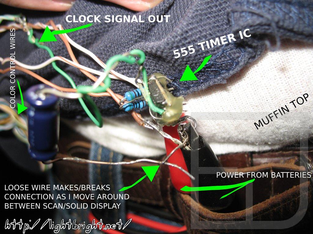
Is that an Arduino/micro-controller controlling that?
I use a beagleboard to display text and animations, but the blinky scanning colorful shows are simply driven by 555 timers! Any microcontroller with at least 4 available outputs can fully address a single 16x16 RGB panel.
Is that going to the music?
Not exactly; It's changing with my movements and I am moving to the music! Or I manually control it as of "circuit v2.0" (i.e. there is no microphone. yet.)
Is that warm to wear?
Not at all, it generates no heat and is basically see-through so wind can attack me and my body heat can escape.
Love it! Let's go into business together!
You do all the work and we split the profits!
At this time I'm not interested in teaming up/partnering with anyone on the production of these panels. But thank you for the interest!
Safety! Have you thought about motor & bi cycle lighting?
Yes, in a way - lighting up is good! But not so much with bright fancy/complex display; there is a condition called "Target Fixation" in which something that is so distracting that you have to watch it causes someone to stare, veer, then collide with you! A little more subtlety would be OK, though!
Where are you based?
I was born, raised, live and work in the San Francisco Bay Area.
Where can I buy one?
Go make one :) BUT... if manufacture these, I'll definitely sell them en masse. Otherwise it's on a comission basis. Stay tuned!
* One of my previous jobs was as a TV-repair technician where I was taught various component (diode, transistor, some resistor) testing and substitution methods. Sometimes I want to go back, it was so much fun diving into circuits all day, diagnosing and repairing them on the spot!
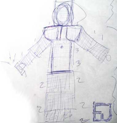
The childish sketch to the right was just a quick run over how many panels I will need to build for 100% coverage. 3 panels are just a hair too short to wrap around my torso end-to-end, but when they are given room to stretch by clipping the grid some, it's perfect. And two fit from my armpit to my crotch making 6 for my torso and waist.
One panel is way too small to wrap around a thigh or calf so I will need two for each, leaving a few inches above my ankle. The panels for my thigh/calf meet right at my knee, which is awesome so I don't have to worry too much about flexibility there.
My shoulders/upper chest area is a little tricky A single panel for each shoulder starting against my neck leaves too much excess sticking out past my shoulder, akin to armor of old. I think I will just deal with it. That leaves a very small area about 8x8 front and back center uncovered. I think a special panel divided into quarters with extending interconnects will have to be made for that.
On my head, two panels make the circumference nicely and the panels are all fairly see-through, so I'll just be a cylinder-head!? Maybe one day I will cut and sculpt 2 panels to the shape of my head...
My ankles & shoes I think I will leave barren.
My only concern about 100% coverage are the areas that would rub together like the insides of my arms and thighs. So instead of walking around like a zombie I may have to forgo one panel on each inner thigh and the inside of my upper arms - just mount them half-around unless I devise/find some plugs I can wrap around each LED to make them more sturdy, less prone to bending and catching on things or each other.
The small circle on my breastbone area is a tiny webcam with a fish-eye lens and excellent low-light sensitivity/night vision to record reactions from. It's very thin and the lens fits nicely between the grids & wiring.
The device in my hand with the radiating lightning bolts is a concept I'm aiming for* which will be a PDA controlling the animations of the suit. It (the suit) will be wireless (WiFi) controlled, i.e. let anyone with a WiFi-enabled device control it... With restrictions of course; there'd have to be a queue with an allotment of time per person/device so everyone can play. Perhaps the computer controlling the suit that is accepting the connections will point all DNS queries to localhost or redirect every HTTP request to http://lightbright.net and http://lightbright.net will be the on-board HTTP server! In concept this all sounds very easy to implement!
* I have successfully implemented the WiFi controls entirely to how I'd imagined them! Totally awesome!
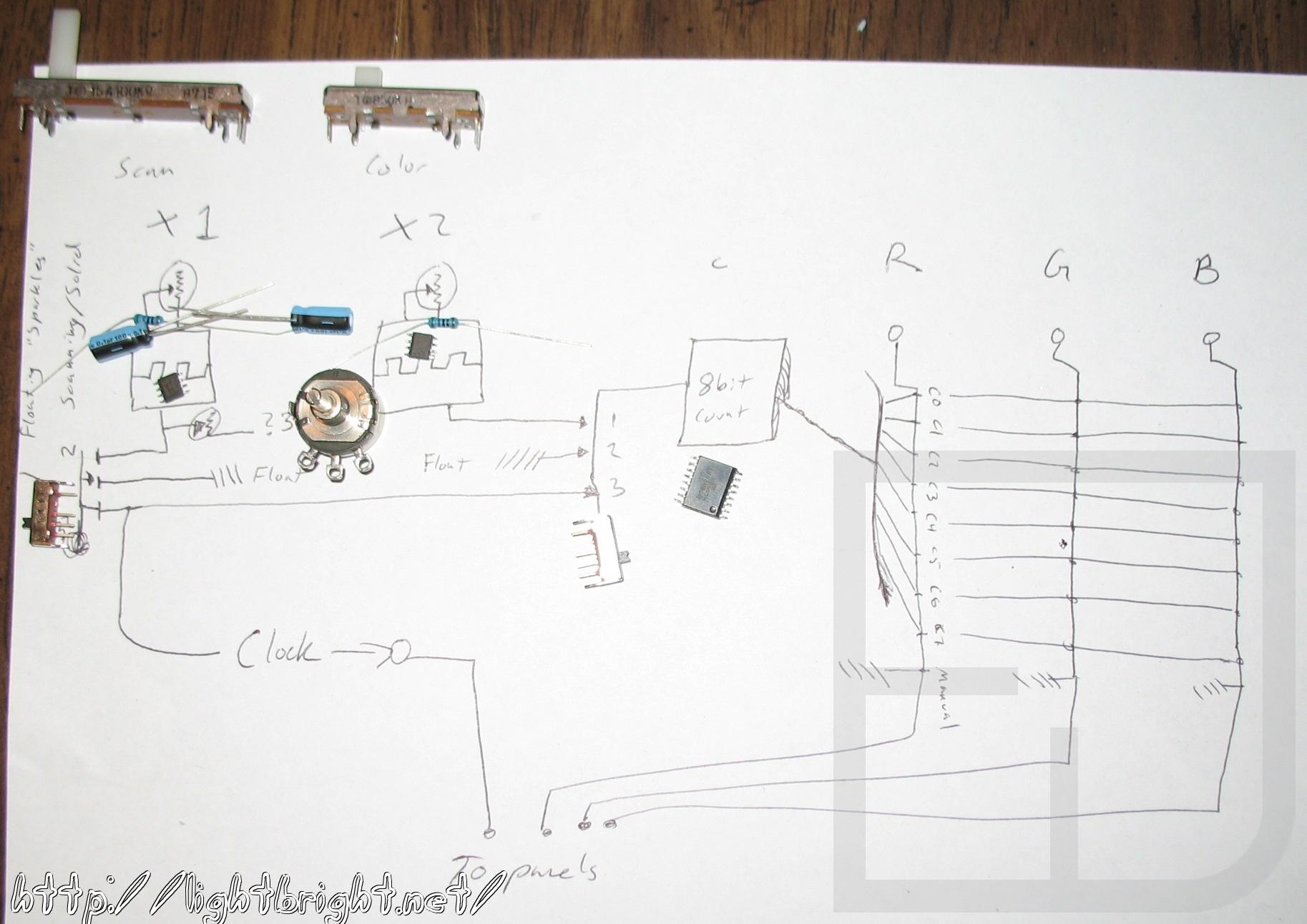
The sketch above was me figuring out how I want to address multiple panels with possible varying brightness per-pixel from a single serial signal. I'm thinking I need to create three separate Pulse Width Modulation (PWM) circuits for each color on each panel if I want to do the varying brightness. The sketch doesn't reflect any kind of finished or working circuit, but I thought some of you might find it interesting to look at. Basically it is trying to figure out how to divide the clock signal up with X-bits per color (a value to be passed to a PWM driver), then after X-bits passed to switch to the next panel, etc. finally sending an advance-pixel signal to all panels. I'm also thinking about having each panel contain its own memory chip to keep an image refreshed while another panel is being updated to keep down any flicker and have a fuller, more fluid display. At the moment all signals are just in parallel. I've started adding memory chips to each panel so they are able to self-maintain an image while another panel gets updated. This was super simple to implement and looks flawless!
Here are the new manual controls in their planning stages a few days before Coachella '10. Instead of the single timer used for the vertical scanning, I'm adding another 555 timer to feed an extra 8-bit counter which will control color cycling so the scan rate and color change rate can be run independently. I did this because I know I can create interference/moire patterns if I get the color and scan frequencies near each other or their harmonics. I have some multi-position slide switches so I can choose/redirect the clock sources for the vertical scan and color change rate.
For example, the vertical scan may be clocked from the vertical scan timer, clocked from the timer through a variable resistor, or floating. When I run the clock signal through a resistor it distorts in neat ways! The color change rate can be clocked from either the independent color clock, the vertical clock or floating. The actual RGB color lines I plan to run through a multi-position switch with at least 10 poles/positions. Each pole would be a different output from the binary counter, then manual (touch sensitive), and always on.
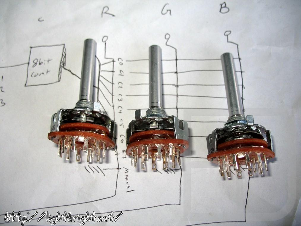
I couldn't find any such switches for a reasonable price from my usual sources in time for Coachella, so I just soldered the red to out7, green to out6 and blue to out5 of the counter IC. This gives a horizontal pattern of 2-lines-thick black (off), blue, green, cyan, red, purple, yellow, white. Anyone recognize the color order? :) I later found 12-position rotary switches, but they still weren't very cheap. I got 3 of them and wired them up to the 8 bits of the counter, manual/off, on and 2 left over for future discretion.
First iteration of controls: c2008-2010
The original plan was to just have the lights sequence only at first,but then the capacitor on the 555 circuit got disconnected the timer went full-force to provide the appearance of a solid-on panel. I went with this accident and purposefully let one leg of the cap hang free so I could manually change between solid and scan. With a bit of futzing around I could make the connection just-so that it would connect and disconnect as I moved around, so as I walked or danced the panel was in sync with my movement! If I wanted the panels to sparkle, I would disconnect the clock line and use my spit to make the connection, thereby leaving the clock line floating but with some influence from the 555 timer.
I had my skin connected to negative my means of a cliplead tucked under by belt, and the color control lines for the panels were sensitive enough that my touching them would turn a particular color on (with the help of my having grounded myself to the circuit). If I didn't feel like holding those wires, I just tucked them under my belt and the colors stay on.
Second iteration of controls: c2010
I stepped up the capabilities a bit after doing some experimenting on my protoboard, mainly by taking an idea that I could do rudimentary patterns by tying the RGB enable lines to the output of a counter. I also wanted control over the scan speeds which would be easily accomplished by replacing one of the resistors in the 555 timer circuit with a sliding potentiometer (POT). Then I thought it would be nice to add a second 555 timer/pot specifically for advancing the color counter and using a switch to select if the color counter should be advanced from the primary 555, or from its own separate 555 timer. Doing this allows me to also set the two timers near the frequency but not the same, causing some cool harmonic/interference patterns. The actual 555 timer ICs & their capacitors are hot-glued underneath each sliding variable resistor. I soldered the R, G and B lines to the MSB bits 7, 6, 5 respectively of the 8bit counter, giving me 2-lines thick, horizontal of each possible combination all-on-color.
I also added a pot for the main clock line so than I can adjust the resistance/"sparkle" level. This option is also selectable via switch. I actually finished putting this together (soldering in a moving van!) on the drive down to Coachella '10 and carved out a box to put them in while setting up our campsite, sealed it up in tape... much to the confusion of the Mounties patrolling the campground, LOL.
Third iteration of controls: c2010-2011
Just a slight improvement on the one above, as I realized I forgot to put an autonomous pattern changer on the controls (the loose wire). On the wires routing through the clock sparkle pot, I added a few rings of loose wire to rattle around the pins as the controls are jostled by my movement, going between sparkle and scan or solid depending on the main clock speed selected. I also tried this on the end of the slider to switch between solid and scan only, but it was too exposed and broke easily (for now), so that piece is manually actuated.
I also acquired a few several-position (12) rotary switches which I routed the RGB enable lines through to each of the outputs to the color counter, allowing me to select different patterns on each color. Off, always on, or 1,2,4,8 lines-thick horizontal or vertical bands.
Fourth iteration of controls: 2011
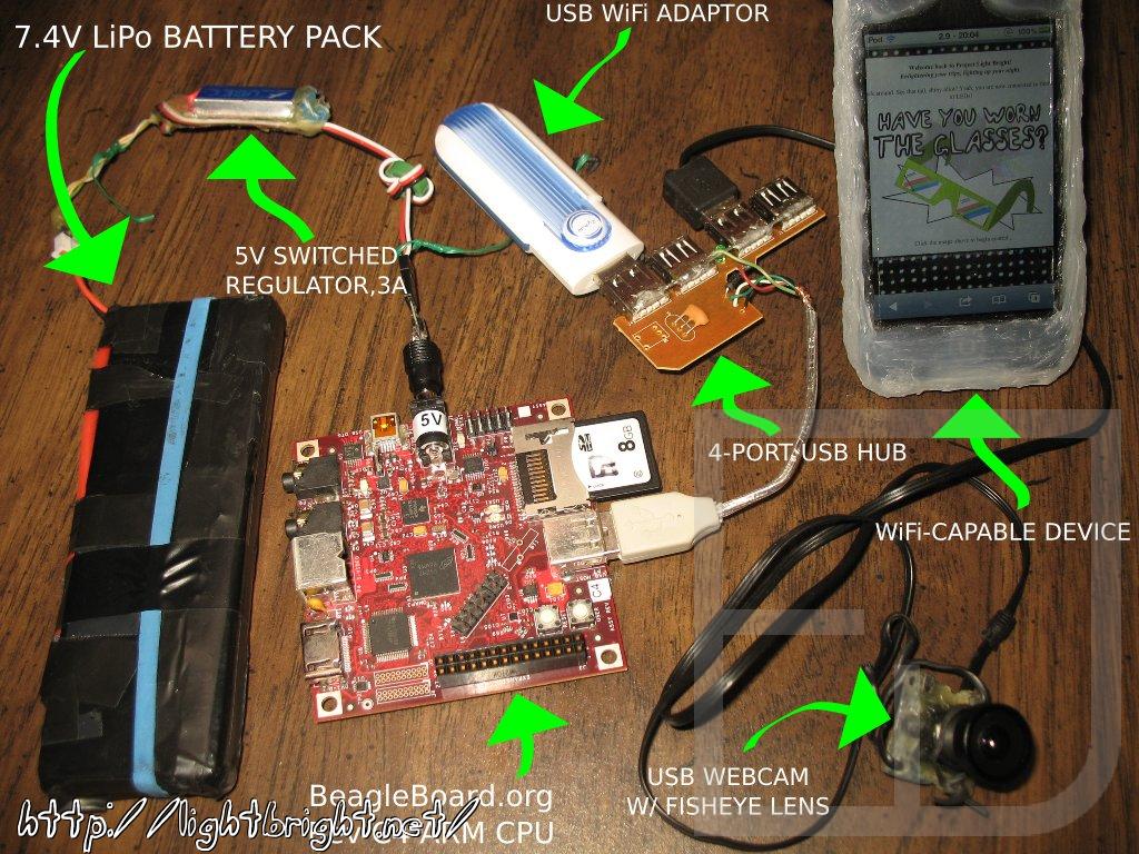
I plan to go all-BeagleBoard.org in my final iteration, using the above as a stand-by in case of failure. As for controls, I will take advantage of the WiFi and webserver on the BeagleBoard to use my iPod to command the panels. That's right, I will control the LED suit with my iDevice (iPod, iPhone tested!)! I've moved up to using a BeagleBoard.org as a WiFi controller and pocket computer. As the WiFi is an ad-hoc connection at the moment, android phones won't connect or see it. Blackberry testing is pending. Laptops works splendid but are bulky, of course. I've managed to get the WiFi to go into master mode to act as an access point.
The GPIO by default are set aside for MMC2, UART2, BSP1/3, I2C2 which I patched out all but MMC2 (in case I want a second SD card slot) of the kernel so that I may use them for my own purposes. This freed up 12 GPIO pins for my hacking pleasure, 22 if I decide to patch out the MMC2 pins. I have the pins configured as R,G,B,Clock,V-Sync,Write, and 6bits panel addressing. I am in the process of adding SRAM to each panel, these address lines will determine if the SRAM will accept new data (write-enable pins).
Attached to the USB port I've plugged a hub to connect a WiFi dongle and micro WebCam. Running on the board are a custom-compiled Linux kernel 2.6, Apache with PHP and SQLite database from the Aangstrom distribution to serve up my mobile web content, and a custom program written in C to communicate with the GPIO for controlling the LED panels with some (hopefully) sweet animations. I've fabricated a sturdy sealed case to put it in to protect it from tweakers, the elements, beer-pourers and people bumping into or tackling me. Yes, this has all happened.
Demonstration here!